Axle Alignment System

Designed & Developed exclusively for front axle Manufacturers to Pre-align Toe in a dynamic axle assembly line.

  • Wireless Communication using ZIGBEE RF Technology
  • Total cycle time of 70 seconds is all it takes for the entire process
  • Compact design, occupies less floor space
  • Software guided process sequence
  • Alignment summary report with Xmr chart for statistical control and process capability analysis
  • Automatic data pushing (alignment results) to Manufacturer MES server
  • Battery powered Camera Hub adapters with Auto-charging facility in idle condition, suitable for continuous 16 hours operation
    once fully charged for 8 hours
  • Display of Toe in “degree min”, “degree”, “mm/M”, “mm”
  • Data manager software for storing Axle alignment results with reference to Axle ID / Date for future reference.
  • Customized Toe setting software along with Data management software are exclusively developed to suit vehicle manufacturer’s requirement
  • The system will measure individual toe of each axle hub independent of the distance between the axle hubs.
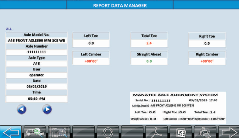
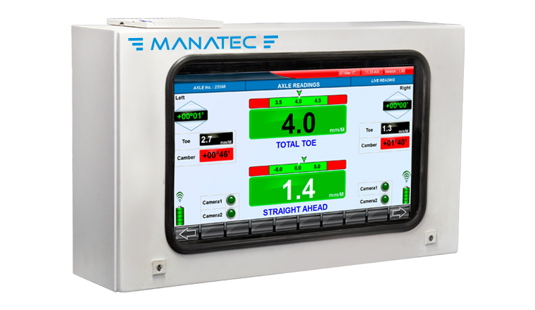
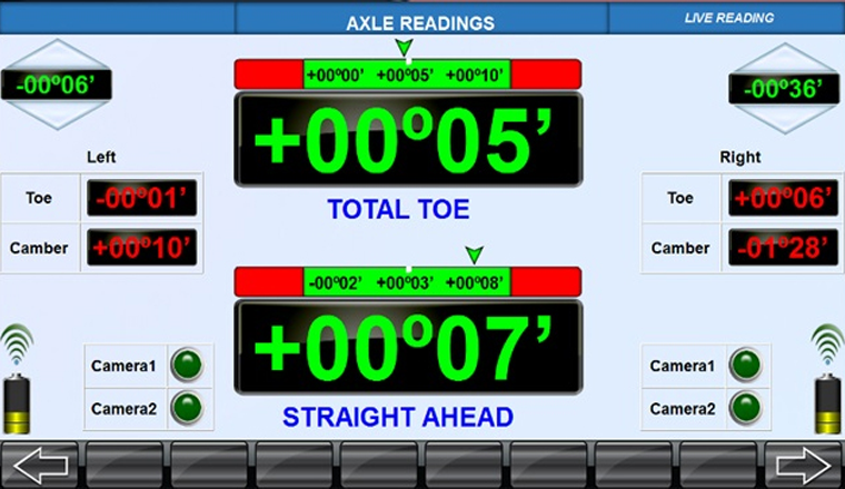
  • The proprietary software computes everything internally and displays relevant results like Straight Ahead, Individual Toe, Total Toe and Camber
  • Measurements can only be stored when all the values are within the tolerance
  • Max Turn (Lock angle) measurement (Optional)

FEATURES​

ZIGBEE Technology
Wireless communication using ZIGBEE RF Technology.
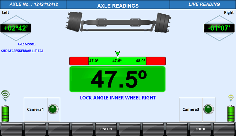
Live Measurement Screen
Parameters such as Toe, Individual toe, Camber & Straight ahead are displayed on the single screen.
Lock Angle (Max Cut) Measurement
The cameras will be incorporated in the hub adaptors itself, hence no separate (ceiling) setup is required for the system to measure the Lock angles.
Data Manager Software
Data manager software for storing Axle alignment results with reference to Axle ID / Date for future reference.
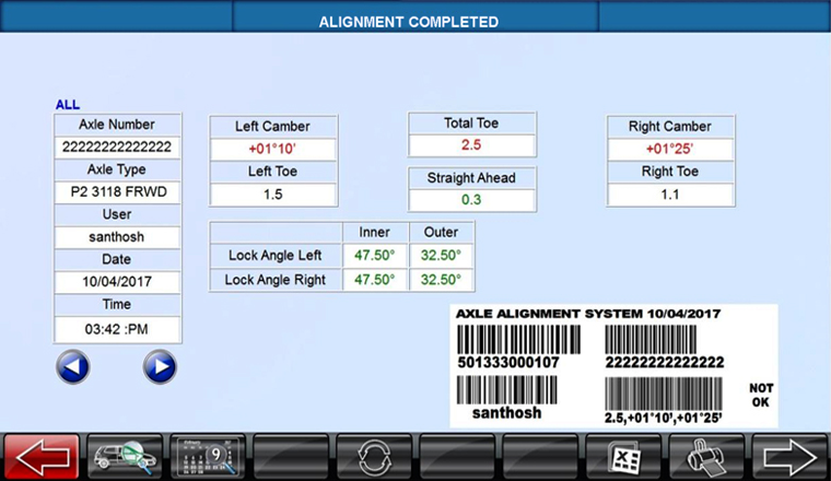
Alignment Results
All results in one screen.
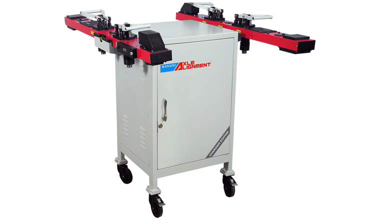
Charging Unit
A battery charging unit is provided to charge the camera hub adaptors and inclinometers during idle condition. The unit also has provision for charging the spare batteries.
Secondary Monitor
Displaying Alignment parameters in larger display for better visibility when viewing from a longer distance.
Barcode Reader & Printer
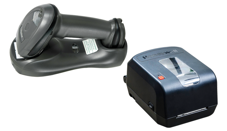
A Barcode scanner is provided for scanning axle information which is used for quick and easy retrieval of specification from the stored database. Measurement results can be printed as a Barcode & pasted over the respective Axle.
PCD Bracket
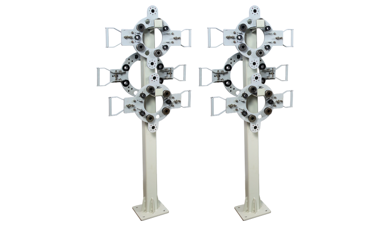
PCD brackets will be provided for mounting the Camera Hub adaptors to different type of axles variant.

TECHNICAL SPECIFICATION

Measurement Parameters Range Resolution Accuracy
Individual Toe ± 30mm 0.2mm ± 0.2mm
Total Toe-in ± 60mm 0.2mm ± 0.2mm
Straight Ahead ± 60mm 0.2mm ± 0.2mm
Camber ± 10° 00' 00° 02' ± 00° 02'
Lock to Lock Angle 25° to 55° 00° 07' ± 00° 15'

CATALOGUE DOWNLOAD

Axle Alignment System

RELATED PRODUCTS

Product Enquiry